Yellow Bullet Forums banner

Dome pressure and manifold pressure ?

27K views 37 replies 13 participants last post by  DigRacer  
#1 ·
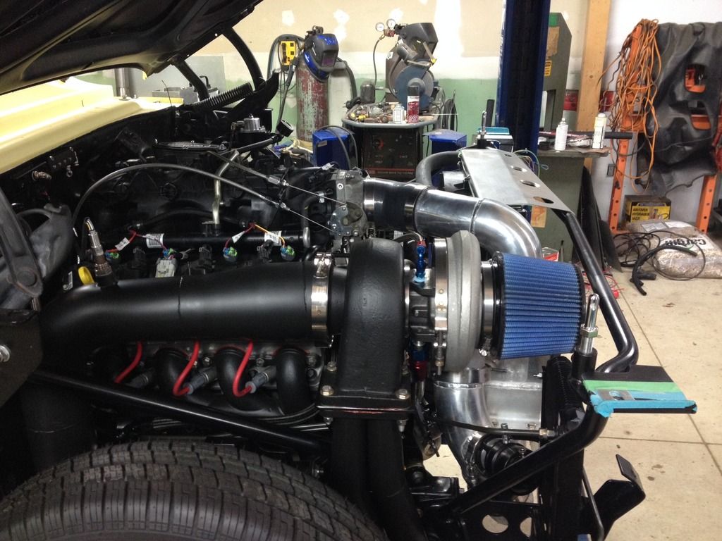
Are these going to be the same? I built a manifold for all my vacuum/boost related tubing. I feed with 3/8 out of the back of my truck manifold, have my MAP and FPR feeding off their own 1/4" line (so they see the same) and then have both gates and the BOV, as well as my boost gauge fed from the manifold. I am adding my holley boost control now, and instead of running my pressure switch all the way up front out of the top of one dome, I was thinking I should be able to just screw it into my manifold. The manifold and the dome pressure should be reading the same, yes? I then just T the two boost solenoids together and run that back to the bottom port (split) of the WG's correct? Then vent both gates to atmosphere?

 
#3 ·
Dome pressure has nothing to do with manifold pressure.

Your wastegate shoild NOT go to the manifold, it goes before the throttle blade, sometimes right on the turbo outlet.

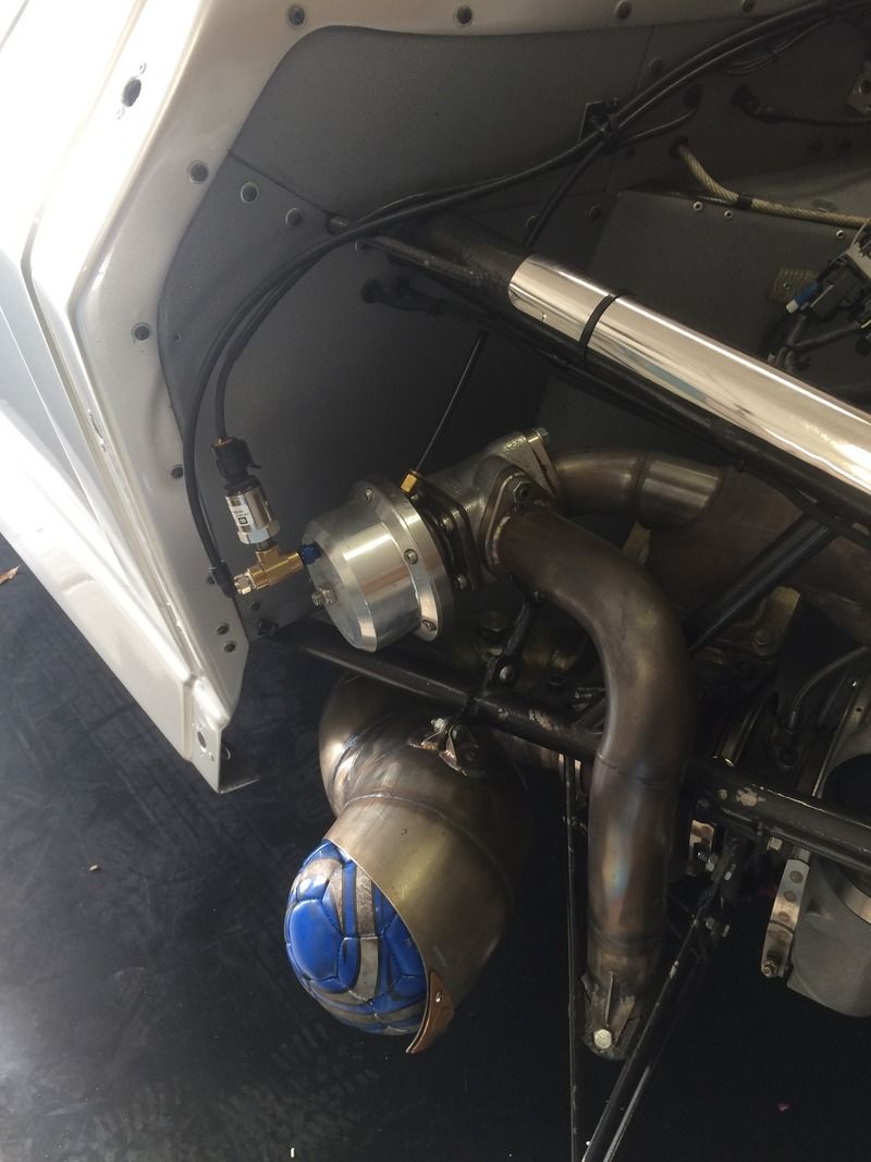
The wastegate should have the reference pressure on the bottom of the gate, not the dome.

Your trying to make everything neat, but you got all your stuff connected wrong as far as the wastegates are concerned.

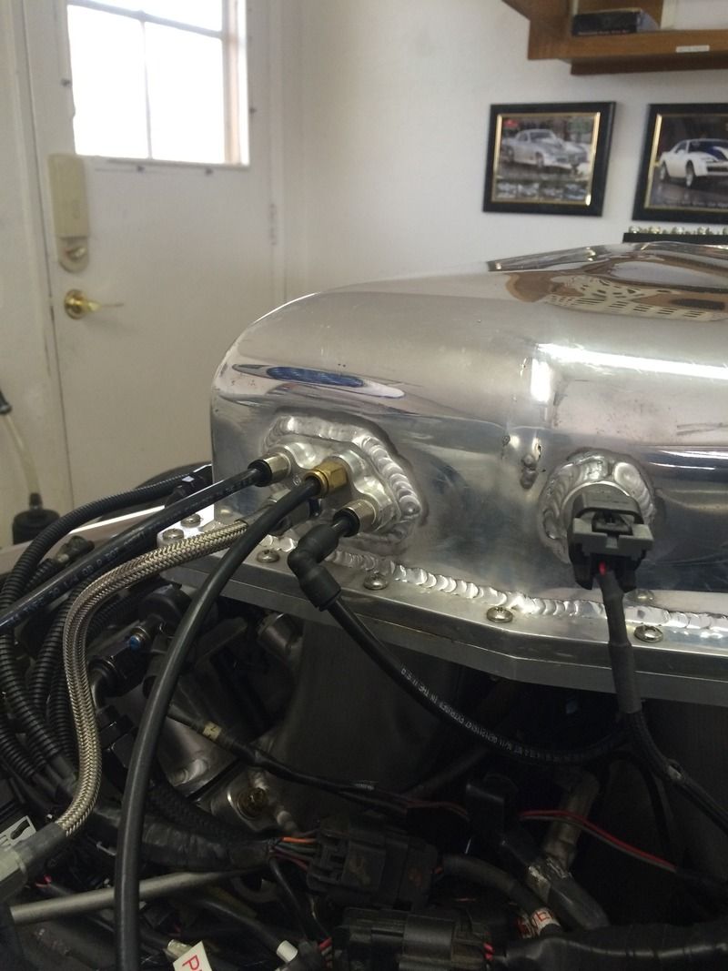
Fix your house connections, mount the sensor in the dome.
 
#5 ·
Your wastegate shoild NOT go to the manifold, it goes before the throttle blade, sometimes right on the turbo outlet.

I was told pull this signal from the manifold to show true boost pressure in the motor. This way any drop from the IC will not affect what reading the computer is being sent.

The wastegate should have the reference pressure on the bottom of the gate, not the dome.

This is how I have it currenty, without boost control.
 
#4 ·
Your dome is going is going to be a regulated leak when the boost control is active. You need your sensor to read what pressure is going in and being bled out of the dome to set up your boost control values. I went right from the port in the throttle body to my gate. It was a metal elbow that went to the valve cover. I pulled the tube out and threaded the hole and installed a barb fitting. I also have a log for all my things that need tubing, but really only my FPR and BOV need to come out of it as ill now be running a display. No need for extra gauges.
 
#10 ·
Used my EPIC photoshop skillz to fix your sketch. redo it like this. will work 100x betterer. IF you only wanna run gate pressure, leave the line off the top of the gates and you wont need the sensor either. NEVER plumb the solenoids into the bottom of the gate like you have done here. boost will be HUGE as it will rely on exhaust backpressure to open the wastegate. might make 50psi or more. perfect on a little 2.5L import not so much a v8


#11 ·
Mad skills! Its currently set up to run on spring only, but now I'm now plumbing my holley boost control in. That's what I'm trying to figure out. I'm reading the holley PDF's on the subject now.
 
#12 · (Edited)
The corrcted one is right.


The way you had it, when you closed the throttle, it sucked the wastegates closed and that is a good way to scatter a turbo. If the RPM's are high ehough, as you close the throttle the wastegate slams shut and puts oll of the last bit of the high RPM exhaust through the turbo, sending its shaft speed sky high.

Wastegates are referenced before the throttle blade. BOV's, FPR, EFI are referenced after (manifold).


Is this going to be a street build? For the track, Co2 is the only way to fly with wastegate control. Without Co2, your asking the wastegate to do something, and hoping there is enoigh pressure available to pull it off. With Co2, your telling the gate what to do, and it instantly does it.
 
#13 ·
But if the throttle closes, the BOV also opens, so the compressor also has no boost anymore. Isn't this exactly the same as what the intake manifold is experiencing? Not trying to be difficult, just trying to educate myself. Street car 75%. Track 25%.
 
#14 ·
The BOV helps, but not how you think. Every factory car, and every professional drag car uses its wastegate pressure from before the throttle, and 90 percent of those use the pressure tapped from the turbo cover itself.

Back to the pressure in the intske tubes. Remeber these are centrifugal compressors, not positive displacement. Turbos are loaded or working when they move air. Whenever airflow stops, the turbo experiances a RISE in rpm due to a lack of load. We use the vacuum cleaner as a basic example. When the inlet on the vacuum is open, motor RPM is low, when the inlet is blocked, RPM us high.

The BOV is a turbo shaft speed reducer because it keeps airflow moving through the turbo, keeping shaft speed low and safe. How you have the wastegate now, your refrencing what the intake is seeing, not what the turbo is outputting. You could easily be 1/3 throttle, and the poor turbo has little airflow and a decent exhaust flow with the wastegate still being stuck shut, which can create very very high turbo shaft RPM.

The turbo needs out a set amount of air pressure into the intake duct, and no more. When we tune, we creep up on boost to set a proper, yet limited amount of pressure in the duct which is being controlled by the wastegate seeing duct pressure. You put a valve (throttle) between the controlling mechanism and its signal. Its like putting a switch an electrical signal, your cutting off the good information when you close the throttle, and actually feeding it bad (vacuum) that it should never see.

There is every disadvantage to how you have it, with zero performance advantage.
 
#17 ·
Another reason I like to feed the bottom port on the WG from the compressor is how short the line is. Less chance of the hose being damaged with such a short run.

In the picture of the vacuum block at the top there is a MAP sensor on the intake. Is there not a 3 bar MAP sensor that will replace it and be more accurate and reliable than one remotely mounted? I too am trying to learn. If I had a way to mount mine directly to the intake it would be there. If there was a failure on any of the hoses on the vacuum block the MAP sensor would still read correctly.
 
#20 · (Edited)
Yes there is. If you look at the picture, directly to the left is my 3bar map, plumbed out of the bottom of my manifold block. There is no 3bar that will fit directly in my truck manifold.
 
#21 ·
So the only thing I can't wrap my head around is how taking my reference from behind the throttle body is different than taking it from in front of the throttle body? The throttle blade closes, and the BOV instantly opens, and my BOV is literally 5" away from the outlet of the compressor outlet, so the excess pressure is instantly dissipated. The pressure behind the throttle body is used up instantly by the motor. So I can't see why manifold pressure coming out of my manifold block, to the bottom of the gates, then the line from manifold block, to my solenoid's, plumbed to the top of the gates along with my pressure switch wouldn't work. I do agree the way I drew my hand drawn print is incorrect, but the above should work just fine, no?

 
#28 ·
Op what kind of wastegate do you have tial will say vacume can damage it but I have never seen it I have ran it both ways with no problems yes it is best they never see vacuum but it don't always work like that lol
 
#33 ·
Did some more searching and found a post from Lance at JGS. While he can't say with 100% certainty, he recommends pulling reference from after the IC and before the TB. He believes the vacuum COULD POSSIBLY deform the seal on the WG piston and shorten the life of the seal. Good enough for me. Thanks all.